Shutter Concepts, Part 1
After spending some time testing lenses, I have chosen to revisit the shutter problem. The goal is to have a shutter system which both minimizes shutter lag (time between trigger and full-open) and exposure time (time that the shutter is not closed). The realistic value to shoot for is a 4.5 millisecond shutter lag and a 1/500 second exposure (which is what Frans has achieved).
The lag time is important because if an insect triggers the camera and the shutter takes too long to open, the insect may be out of the field of view or out of focus by the time the picture is taken. The exposure time must be minimized to reduce motion blur under natural lighting conditions as much as possible—in other words, we want as close to 100% of the exposure lighting to come from the flash.
The size of the shutter is the limiting factor in its speed. Since according to the lens tests the aperture will be f/11 or f/16 (if depth of field doesn’t require an even smaller aperture), the size will not be too large. I wouldn’t mind having a versatile shutter rather than limiting myself to a small aperture size—who knows if I may not want to have some shots with extremely short depth of field.
Traditional iris shutters (like the Ilex Oscillo B I tested before, except with built-in timing mechanisms) have a maximum diameter covered by the shutter leaves regardless of what the aperture diaphragm is set to. In other words, time is wasted with the aperture leaves opening into the area which is covered by the aperture diaphragm. This is not an issue with traditional shutters since under natural lighting the exposure time will increase as the aperture decreases, but since we want it to go as fast as possible regardless of lighting, this timing mechanism is not optimal. For large apertures, this is especially unacceptable—the fastest size 5 shutters have a 1/50 second exposure at the fastest settings.
Although I still plan on repeating the tests with the size 3 Oscillo B, but with higher voltages, I did some calculations regarding various shutter concepts to get an idea of what is possible.
The Swinging Wedge Concept
To minimize lag and exposure, the accelerations must be as high as possible. An iris shutter requires an acceleration to start opening, then (assuming it just “slams” open) an acceleration to start closing. Conceivably then the exposure time could be cut in half by eliminating the second acceleration.
Such a shutter could be made by having a plate shaped like a slice of pizza with a hole the size of the aperture in the center at the edge, with just enough space on either side to cover the lens aperture. In the diagram below, the wedge-shaped plate, which is made to be thin, is shown with an optional wedge-shaped cut (the dotted line filled in white) to save weight. The aperture hole is shown in white, and the dotted circles show how on either side there is enough plate to cover the aperture. In the shutter “closed” position, the lens aperture would sit entirely within one of the dotted circles (A or C). The shutter is opened by pivoting it about the dark grey circle on top, and as the circular hole (B) in the wedge passes through the lens shutter, the exposure is made (the flash would fire exactly when the hole coincides with the aperture—that is, full open position). The wedge then continues to rotate until the lens aperture is completely covered by the second dotted circle region.
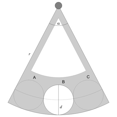
If we leave the radius [tex]r[/tex] of the wedge as a variable, then the minimum angle [tex]\alpha[/tex] it must subtend can be estimated by setting the length of the dotted arc to be three times the diameter [tex]d[/tex] of the necessary aperture. The length of a circular arc is simply the angle it subtends times its radius (which is why the circumference of a circle is [tex]2\pi\times r[/tex]):
[tex]3d = \alpha \left( r – d/2 \right)[/tex]
Note that this equation is an approximation, because we are setting an arc length equal to the length of three straight lines, when in fact we should calculate the angle between the three straight segments and make the wedge fit that dimension.
To maximize acceleration, the inertia of the shutter wedge about its pivot point should be as small as possible. The inertia we are looking for is called the “polar moment of inertia” about the pivot point (in this case, the center of the circle the wedge came from), and is available here (note that that expression is in terms of the half angle). The expression using the full angle of the wedge is
[tex]J_W = \frac{\alpha r^4}{4}\rho t[/tex]
The multiplication by [tex]\rho t[/tex] is to account for the real shutter wedge having thickness and being made of a material with density.
To account for holes, we simply have to subtract the inertia of the corresponding shape. Ignoring the weight-saving wedge-shaped cut out, we only need to consider the aperture hole. The moment of inertia of a circle about its center is (omitting the mass and thickness parameters)
[tex]J_C = \frac{\pi \left(\frac{d}{2}\right)^4}{2}[/tex]
(Note that like area and circumference, it is related to that of the wedge by the subtended angle.)
But in our case, this hole is pivoting about a point which is not the one for which the above moment of inertia is calculated. We can use the parallel axis theorem to find the new moment of inertia:
[tex]J_C = \frac{\pi d^4}{32} + \pi \left(\frac{d}{2}\right)^2\times \left(r – d/2\right)^2[/tex]
and thus the inertia of the shutter is
[tex]J_S = J_W – J_C = \frac{1}{4}\rho t \left\{ \alpha r^4 – \pi \left[ \frac{d^4}{8} + d^2 \left( r – d/2 \right)^2\right]\right\}[/tex]
If we wanted to include the weight-saving wedge cut, and assume its tip is an offset [tex]s[/tex] from the pivot point and its circumference is offset the same amount from the aperture hole, then its inertia contribution would be
[tex]J_{\text{cut}} = -\rho t \left[\frac{1}{4}\alpha \left(r-d-2s\right)^4 + \frac{1}{2}\alpha\left(r-d-2s\right)^2s^2\right][/tex]
Ignoring this for now, we write the expression for the inertia of the shutter by replacing [tex]\alpha[/tex] with its relationship to [text]r[/tex] and [tex]d[/tex]:
[tex]J_S = \frac{1}{32}\rho td \left\{ \frac{24r^4}{r-d/2}-\pi d\left[ 8\left(r-d/2\right)^2+d^2\right]\right\}[/tex]
In our case, [tex]d[/tex] is dictated by the f-number of the lens, and thus [tex]r[/tex] is our only variable. Since the only positive term has an [tex]r^4[/tex] in it, it would seem the best way to minimize inertia is to minimize the radius of the wedge. To minimize the radius, we have to find the shape that most tightly packs the three circles, which should be an equilateral triangle. The “wedge” which then circumscribes this arrangement is the minimum inertia version of this shutter. The shape is shown in the diagram below, which we use to calculate the radius of the plate (we show again an optional weight-saving cutout at the bottom).
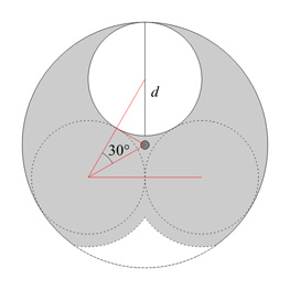
The equilateral triangle that links the circles’ centers has a side length [tex]d[/tex] and a half-angle of 30 degrees. Thus the distance from any corner to the center of the equilateral triangle is the hypotenuse of a right triangle with angle 30 degrees and “adjacent” side equal to [tex]d/2[/tex]:
[tex]h = \frac{d}{2}\sec30^\text{o} = \frac{d}{2}\frac{2}{\sqrt{3}} = \frac{d}{\sqrt{3}}[/tex]
So the radius of the plate is
[tex]r=\frac{d}{2}+\frac{d}{\sqrt{3}}[/tex]
The inertia of the plate itself is the same as the wedge with [tex]\alpha=2\pi[/tex]. The inertia of the aperture hole is the same, but its distance from the pivot changes to [tex]d\sqrt{3}[/tex]:
[tex]J_W = \pi \frac{r^4}{2}[/tex]
[tex]J_C = \pi\frac{\left(\frac{d}{2}\right)^4}{2}+\pi\frac{d^2}{4}\left(\frac{d}{\sqrt{3}})^2 = \frac{11}{96}\pi d^4[/tex]
[tex]J_S = J_W – J_C = \frac{1}{36}\left(7\sqrt{3}+8\right)\pid^4 \approx 1.756d^4[/tex]
The density and thickness were omitted for simplicity.
Even if the “wedge” version has its weight-saving cutout, its inertia will still be higher than that of this minimum inertia arrangement. Note, too, that the inertia in all these could be further reduced by thinning out the dotted circles—that is, they only need to be optically opaque, not structural. Also (obviously) in both cases the radius of the plate would have to be slightly larger so that the shutter opening still has some material around its entire periphery.
Neglecting friction (and the inertia of the actuating mechanism), and assuming constant torque (not likely), the acceleration of the shutter plate can be written as
[tex]\tau = J\frac{d\theta}{dt^2}[/tex]
with [tex]\tau[/tex] as the torque, [tex]\theta[/tex] as the angular position, and [tex]t[/tex] as the time. With 0 for the initial velocity, integrating twice yields
[tex]\theta = \frac{\tau}{2J}t^2[/tex]
Regardless of the angle of the “wedge” plate, the angle that must be traversed for the shutter to be fully open is
[tex]\theta_{\text{lag}} = \frac{\alpha}{3}[/tex]
and we denote it as [tex]\theta_{\text{lag}}[/tex] because the time it takes to traverse this angle from 0 is the shutter lag time. The shutter will be completely closed after twice this angle is traversed, thus for that entire range the shutter is at least partially open. This is not a good measure of the exposure time because at all times except the instant that it is fully open, the aperture of the lens is partially exposed. Still, with this one-swing arrangement, anything that minimizes shutter lag will minimize exposure time, so there’s no point in trying to calculate the exposure time.
With our minimum-inertia geometry (using the numerical approximation to the inertia), the shutter lag time can be written as
[tex]t_{\text{lag}} = 2.712d^2\sqrt{\frac{\rho t}{\tau}}[/tex]
This means that doubling the aperture diameter (increasing it by two stops) quadruples the lag time, quadrupling the thickness or density doubles the lag time, and quadrupling the torque cuts it in half. In reality, the plate should be thicker at the hub so it can withstand the sudden jolts of torque, and as mentioned before, the inertia could be reduced further by not making the aperture covers structural—in fact, one could think of it as a plate with three aperture holes with two adjacent ones covered with a very thin opaque material such as shim stock (one or two thousands of an inch thick). With three aperture holes, the inertia of the plate is 40% lower, and the lag time drops 23%.
To get some ideas of the forces we are talking about, lets assume that the plate is 0.5 mm thick and made of steel (8,000 kg per cubic meter). For a 300mm lens at f/11, the entrance pupil diameter is 27.3 mm, so we can use that for [tex]d[/tex]. The required torque to result in a lag time of 1 millisecond is 16.3 Nm (12.0 foot-pounds). If we use the inertia of our three-hole plate (ignoring the thin material to obscure two of the holes) the torque requirement drops to 9.6 Nm (7.1 foot-pounds). If we want to cut the lag time in half, we need four times as much torque. The Kodak 14″ Commercial Ektar has an Ilex #5 shutter on it, whose maximum opening is 64.1 mm. At this size, the torque required for the single-hole disk for 1 millisecond lag is 496 Nm (366 foot-pounds). A Porsche 911 Carrera puts out 370 Nm (273 foot-pounds) of torque at 4250 RPM. For this last case, at the instant the shutter is fully open, the wedge is moving at around 4200 radians per second (40,000 RPM). Note that even for a more civilized 4 millisecond lag, the disk will be spinning at 10,000 RPM when the shutter is fully open—is it even close to possible to achieve this?
More soon….
About this entry
You’re currently reading “Shutter Concepts, Part 1,” an entry on Insect Camera
- Published:
- 04.11.07 / 8pm
- Category:
- Shutter
No comments
Jump to comment form | comments rss [?] | trackback uri [?]