Variable Voltage Capacitor Charger
In one of my many discussions with Sam, we both discovered that the output voltage possible with a given transformer varies substantially with the frequency of the input signal. This means that one can build a variable voltage capacitor chargers by varying not the input voltage but the frequency of the charging pulses. As an example, a transformer with a 300:1 turn ratio with 1.5V pulsing on the primary will not always putout 450V (or 450V minus losses, or whatever). It depends quite drastically on the frequency of the pulses.
This has some advantages. First, as will be seen below, varying the frequency is very easy. This is especially so, because varying the voltage is not too easy. Most of these flash circuits essentially have the batteries in short circuit, that is, there is no current-limiting resistor. If you try to put a voltage regulator in its place, the behavior will be completely different (if you can get it to work), because the circuit expects the battery voltage to drop as more current is drawn.
As I was learning about strobes, I started looking more deeply into the Sunpak 622 schematic, and I could see the similarities between it and the disposable strobes. After reading that the recycle times with the Sunpak AC adapter are actually slower than with batteries, I wondered if I could just put a DC supply in place of the batteries and achieve a super fast recharge. The biggest AC adapter I had was something like 6A at 9V, and it was constantly cutting out (internal protection, I guess). By the time I added enough resistance (long wires) between it and the flash, so that it could run continuously, the recharge time was not all that fascinating.
Then I finally realized I had a use for the 5V, 40A supply that was on sale at the Electronic Goldmine. I have to say those guys are a thing of beauty. Anyway, that supply can recharge two 622’s to full power simultaneously in less than 10 seconds. Not only is that fantastic, but the whine of the two flashes plus the supply working hard is very much reminiscent of the Ghost Busters’ ghost zappers.
So back to the task at hand—being able to vary the output voltage of a flash capacitor charger by not having to deal with the input voltage at all was a blessing. To try it out, I built a simple circuit with a 555 timer and a transformer off my numerous disposable cameras.
There is plenty of 555 stuff on the web. But none is as useful as this circuit simulator. With it I quickly picked the components I needed to start playing.
The resulting circuit is below. I don’t have any information on the transformer (orientation, number of turns, or anything). Suffice it to say it came from a Kodak camera and its characteristics are not important for this exercise. For simplicity, I was running the 555 off a DC power supply and the capacitor charging from a single AA cell (just like in the disposable cameras).
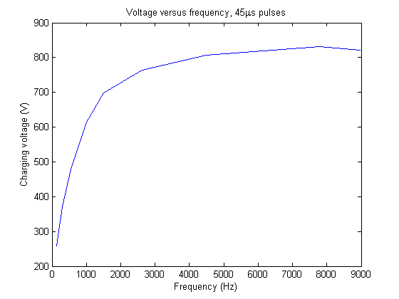
(Note: the schematic above and the text in this paragraph were edited for small errors on 2008-12-20. The schematic did not show a necessary connection between pins 2 and 6, and the description had reversed the roles of R2 and R4.) First, forgive me for the ugliness and confusion of the schematic. I don’t have much practice drawing them, and I’m trying to learn Eagle at the same time. Anyway, there are two adjustable quantities in the circuit: the input [to the transformer] pulse width (varied by changing R2) and the input frequency (varied by changing R4). Without getting into any calculations, I used the simulator mentioned above to test out some values and then used what I had in my bins for the circuit. I monitored the input with my oscilloscope and the capacitor voltage with a multimeter. The minimum pulse width achievable was 45 microseconds; I could vary this up to more than 1.7 milliseconds. The frequency range was from around 140Hz to 9kHz.
As expected, the pulse width does not make too much of a difference; the transformer steps up the voltage according to derivatives of voltage in time. With the really long pulse widths the voltage actually dropped (comparing to the same frequency); I suspect it was because it was draining the battery more between pulses—I don’t really know. The drop is negligible anyway. When I do this again, I will see if I can go shorter than 45 microseconds and see what the difference is; I suspect at some point inductances and capacitances will prevent the pulse from even happening and performance will drop considerably.
For the capacitor I used a 1000V 4700pF ceramic, simply because it charges very quickly, and because I didn’t have anything big that could go to 1kV or higher. In any case, here are the results:

Impressed? I am. The purpose of this circuit will be to test some capacitance/voltage/bulb combinations. I may have to fork out some cash for some more expensive capacitors, because of the ones I have, only one goes to 800V.
About this entry
You’re currently reading “Variable Voltage Capacitor Charger,” an entry on Insect Camera
- Published:
- 23.08.08 / 7pm
- Category:
- Flash

No comments
Jump to comment form | comments rss [?]