Shutter Concepts, Part 2
We continue our discussion on shutters of the spinning “wedge” concept now. Last we left it, we had some discouraging numbers—for a lag of 4 milliseconds, the wedge would have to be spinning at 10,000 RPM at the instant the shutter is full open.
But we have minimized the inertia of the wedge by making it a disk, and, assuming a constant torque output from our actuator, this is the way to minimize lag and exposure time. Beyond this, one idea is to add a second wedge rotating in the opposite direction. The sequence below shows the shutter opening.
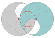
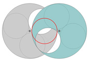

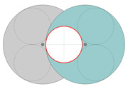
Whereas before the angle from closed to full open was 120 degrees, now it is less than 60. This should save us some time. The diagram below shows us how to calculate this exact angle.
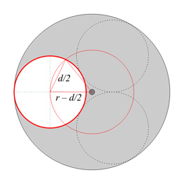
Each disc much turn so that the center of its aperture hole is on the edge of the lens aperture for the shutter to be fully closed. The triangle shown can be used to find this angle; it is an isosceles triangle with base [tex]d/2[/tex] and sides [tex]r[/tex]. Thus we can write
[tex]\sin\frac{\theta_{\text{lag}}}{2} = \frac{d/4}{r – d/2}}[/tex]
and taking [tex]r[/tex] from our previous derivations,
[tex]\sin\frac{\theta_{\text{lag}}}{2} = \frac{d/4}{d/\sqrt{3}} = \frac{\sqrt{3}}{4} \approx 0.433[/tex]
And thus
[tex]\theta_{\text{lag}}\approx 51.32^{\text{o}}[/tex]
Furthermore, our wedges need no longer be disks, since they are not rotating as far anymore. With the figure below, we can find what angle of “disk margin” we need for the two wedges to completely cover the aperture when the shutter is closed.
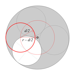
Using the figure, we see that
[tex]\sin\theta_{\text{margin}} = \frac{d/2}{r – d/2} = \frac{\sqrt{3}}{2}[/tex]
So [tex]\theta_{\text{margin}}=60^{\text{o}}[/tex] exactly. This means that now the wedge has to subtend a total of [tex]\left(51.32^{\text{o}}+60^{\text{o}}\right)\times 2 = 223^{\text{o}}[/tex] if we want to the shutter to be bidirectional. The angle could be reduced by a bit less than 60 degrees if we decide that we can reset the shutter between shots (in other words, if we allow it to have a margin only on one side of the aperture hole).
So we have reduced the angle from closed to open by more than half, and reduced the inertia of each shutter blade by quite a bit, too. What effect does this all have on performance? With the smaller wedge angle,
[tex]J_S \approx 0.949d^4\rho t[/tex]
which is 54% of what it was before. Our new expression for the lag time is
[tex]t_{\text{lag}}\approx 1.304d^2\sqrt{\frac{\rho t}{\tau}}[/tex]
which is 48% of what it was before. For 1 millisecond lag of the full aperture of a #5 Ilex, the torque required is now “only” 115 Nm (84 foot-pounds), an amazing 23% of what it was for the single wedge shutter (remember we are assuming we have two independent actuators here; with a single actuator we get 46% as much as before). For 300mm at f/11, the required torque is 3.8 Nm (2.8 foot-pounds) for 1 millisecond and 0.24 Nm (0.18 foot-pounds) for 4 milliseconds. The speeds are still insane, but less so—for 1 millisecond lag the shutter is going at 17,100 RPM when full open, and at 4 milliseconds it is going at 4,280 RPM.
Perhaps adding a third or fourth blade will help even more. The geometry is bound to get complicated, and the law of diminishing returns should strike soon. But first, we should discuss other ideas that don’t rely on force for acceleration.
About this entry
You’re currently reading “Shutter Concepts, Part 2,” an entry on Insect Camera
- Published:
- 08.11.07 / 11pm
- Category:
- Shutter
No comments
Jump to comment form | comments rss [?] | trackback uri [?]